This Lab is to summarize the steps how to configure BGP over IPSec on FortiGate firewalls using Custom VPN Creation Wizard.
Custom VPN creatation wizard is the most common used VPN creating wizard if you are create a tunnel between FortiGate and other verndor’s device. You can easily convert FortiGate or Cisco VPN template created tunnel to custom tunnel from Web Gui.
Diagram
Test Drive is not available anymore after May 2024 based on my observation. You will need to spin up another Fortigate VM in your own subscription. You can refer to this post to get a free Fortigate VM.
Start Azure Fortigate Test Drive Environment
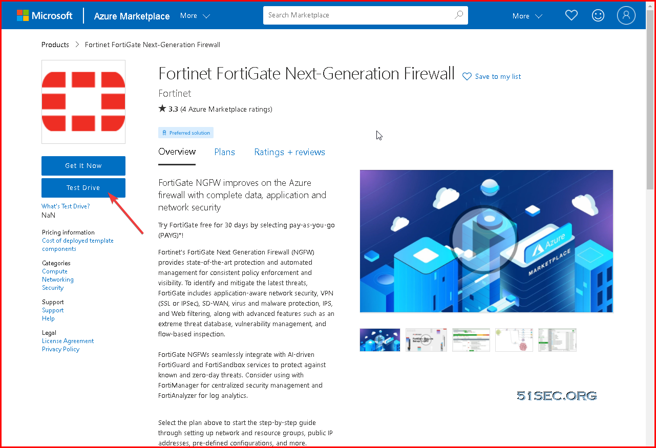
1 Go to https://azuremarketplace.microsoft.com/en-us/marketplace/apps/fortinet.fortinet-fortigate?ocid=FortiGate_202105_landingpage_en-us or https://www.fortigate-azure.com/. Choose a Test Drive, sign in and agree to the terms of use.
Note: Test Drive is not available anymore. [May 2024]
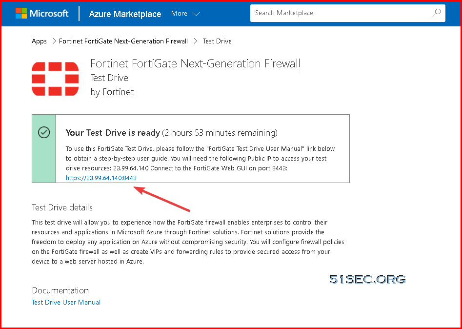
2 After system complete the provisioning, you will get a page to tell you Your Test Drive is ready. The testdrive lab will last for three hours.
Once you complete the form, your Test Drive will start deploying. In addition to the webpage information, in a few minutes you will also get an email notification that the environment is ready. Just follow instructions in the webpage or in the email, and you will be able to access a fully provisioned and ready to use environment.
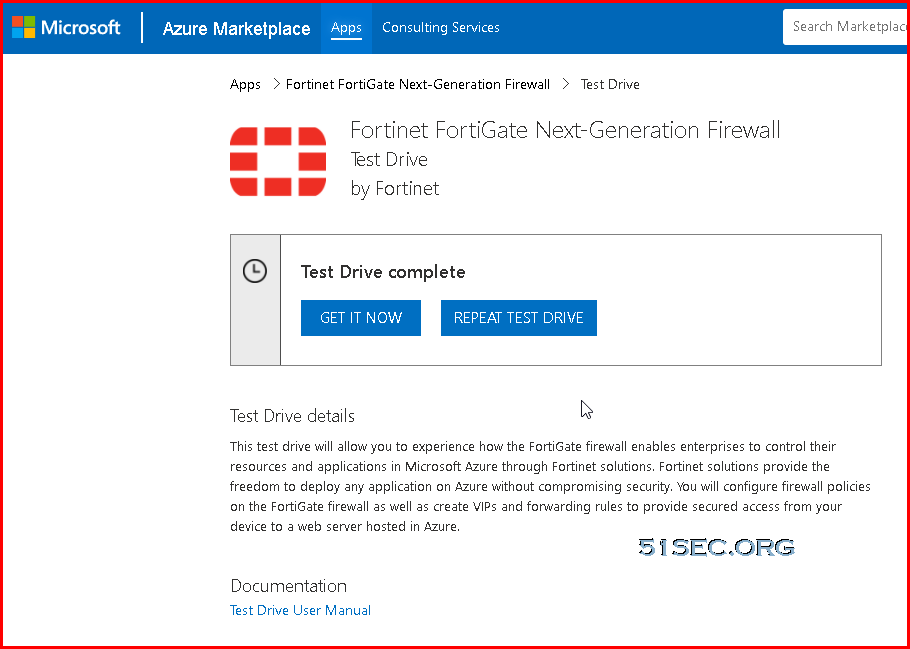
3 After three hours if you have not completed the test drive use case, you still have a chance to repeat test drive to try it again.
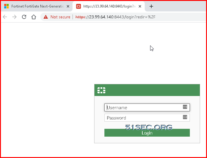
4 When the Test Drive is ready click on the FortiGate link to open the GUI.
- username: ftnt-testdrive
- password: Fortinet@123
Create IPSec VPN Using Custom VPN Wizard
1 VPN Creation Wizard – Choose custom
Pre-shared Key & IKE v1 Main Mode & Phase 1 Proposal
Phase 2 Proposal
2 Complete VPN Configuration on both sides.
3 Create bi-directional Firewall Policy rules
On NetSec site, I have to enable NAT on the rule which allows tunnel traffic to lan as show below. That is because ip forwarding was not enabled on the LAN interface.
Enable IP Forwarding on LAN interface of FGT:
4 Create static route
Based on FortiNet Doc: https://docs.fortinet.com/document/fortigate-public-cloud/6.2.0/azure-administration-guide/609353/network-interfaces-and-routes
5 Test from Test site to Netsec site
C:\Users\netsec>tracert 10.254.0.9
Tracing route to 10.254.0.9 over a maximum of 30 hops
1 1 ms <1 ms <1 ms 10.1.1.4
2 * * * Request timed out.
3 8 ms 7 ms 7 ms 10.254.0.9
PS C:\Users\netsec> Test-NetConnection -ComputerName 10.254.0.9 -Port 22
ComputerName : 10.254.0.9
RemoteAddress : 10.254.0.9
RemotePort : 22
InterfaceAlias : Ethernet
SourceAddress : 10.1.1.5
TcpTestSucceeded : True
Traffic log can be found from page Log & Report – Forward Traffic
Enable BGP
BGP Diagram
Add Interface IP address to the tunnel interfaces
Create BGP Neighbours
BGP Routes from Dashboard -> Network -> Widget: Routing
Route Filtering and As-path for failover
NETSEC-FGT # show router route-map
config router route-map
    edit "OUT-TO-MPN"
        config rule
            edit 1
                set match-ip-address "OUT-TO-MPN"
                set set-aspath "65515"
                unset set-ip-prefsrc
            next
        end
    next
end

NETSEC-FGT # show router prefix-list
config router prefix-list
    edit "OUT-TO-MPN"
        set comments "PRE-PEND"
        config rule
            edit 1
                set prefix 10.254.0.0 255.255.0.0
                unset ge
                unset le
            next
            edit 2
                set prefix 10.111.1.0 255.255.255.0
                unset ge
                unset le
            next
        end
    next
end
Configure route map out OUT-TO-MPN
Final BGP configuration on Site 1’s Fortigate firewall
Troubleshooting & Diag
Tunnel Interface will not be able to ping each other
jyfgt # get router info bgp summary
jyfgt # get router info bgp neighbors
Understand IPSec Tunnel Interface
An IPsec tunnel interface is a Layer 3 logical interface. It supports dynamic routing. All packets including multicast packets that are routed to an IPsec tunnel interface are IPsec protected.
The IPsec tunnel interface has the following advantages:
-
Simplified configuration—The IPsec tunnel interface is easier to configure compared to using access control lists (ACLs) to identify protected packets. The IPsec tunnel interface improves network scalability and reduces maintenance costs.
-
Reduced payload—The IPsec tunnel interface requires less protocol costs and uses less bandwidth than IPsec over GRE and IPsec over L2TP, which require a GRE header or L2TP header to be added to each packet.
-
Flexible service application—You can apply a service such as NAT or QoS to packets before or after they are encrypted by IPsec. To handle packets prior to IPsec encryption, apply the service to the IPsec tunnel interface. To handle IPsec encrypted packets, apply the service to the physical outbound interface.
Operation of the IPsec tunnel interface
IPsec encapsulation and de-encapsulation occur on IPsec tunnel interfaces. Figure 53 shows how a clear text packet arriving at a router is forwarded to the IPsec tunnel interface, encapsulated, and forwarded out.
Figure 53: Encapsulation process of a clear text packet

-
The router forwards a clear text packet received on the inbound interface to the forwarding module.
-
The forwarding module looks up the routing table and, if the packet must be IPsec protected, forwards the packet to the IPsec tunnel interface. The original IP packet is encapsulated into to form a new IP packet. The source and destination of the new packet are respectively the source and destination address of the tunnel interface.
-
The IPsec tunnel interface encapsulates the packet, and then sends the packet to the forwarding module.
-
The forwarding module looks up the routing table again and forwards the IPsec-encrypted packet out of the physical outbound interface that is associated with the tunnel interface.
Figure 54 shows how an IPsec packet is de-encapsulated on an IPsec tunnel interface.
Figure 54: De-encapsulation process of an IPsec packet

-
The router forwards an IPsec packet received on the inbound interface to the forwarding module.
-
Identifying that the destination address of the packet is the tunnel interface and the protocol is AH or ESP, the forwarding module forwards the packet to the IPsec tunnel interface for de-encapsulation.
-
The IPsec tunnel interface de-encapsulates the packet, and then delivers the resulting clear text packet back to the forwarding module.
-
The forwarding module looks up the routing table, and then forwards the clear text packet out of the physical outbound interface associated with the tunnel interface.
References
- Fortigate Doc : Azure VM – Network interfaces and routes : https://docs.fortinet.com/document/fortigate-public-cloud/6.2.0/azure-administration-guide/609353/network-interfaces-and-routes
- https://blog.51sec.org/2022/01/deploy-fortigate-firewall-with-trial.html


